CNC Lathe Internal Grooving Process
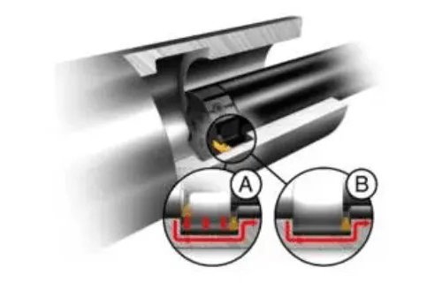
The two main challenges in internal groove machining are excessive extension of the guide rod and poor chip removal. Excessive extension can lead to deflection and vibration issues. Vibration and poor chip removal can cause insert breakage. Difficulty in chip removal can also lead to poor surface finish. The most common internal groove machining process is radial grooving; however, multi-groove turning (A) and feed-in turning (B) can also be used.
1. Tips for Internal Grooving Applications
High-flow precision coolant can improve chip control and evacuation. Using smaller tool bars can enhance chip removal but may reduce stability. To avoid vibration, tools should have the shortest possible extension and appropriate cutting geometry. Using narrower inserts for multiple cuts can help avoid vibration. For final finishing operations (A), internal grooves can also be machined with a single cut followed by feed-in turning (B). Start from the bottom and work from the back of the hole to the front for optimal chip removal. Using smaller insert widths and nose radii can reduce cutting forces.
For precise low-vibration machining, different tool bars should be selected based on the extension length:
For extension lengths 5∗𝐷≤𝐿≤7∗𝐷,use carbide-reinforced anti-vibration bars. For extension lengths 3∗𝐷≤𝐿≤6∗𝐷, use anti-vibration bars or solid carbide bars. For 𝐿≤3∗𝐷, use steel tool bars.
2. Internal Grooving Process
2.1 Radial Feed Roughing
Always start from the point closest to the hole bottom (1) and work outward, leaving space for chip evacuation. Use the recommended feed rate. Subsequent cuts (2 and 3) should be 0.5–0.8 times the insert width. As cutting forces will be lower, you can increase the feed rate by 30-50%.
2.2 Side Roughing
Side turning offers better chip control and breakage. Start from the point closest to the hole bottom and work outward to the entrance. Do not feed from the shoulder, and leave a 0.2 mm step between each pass.
Side turning is more stable than radial feed cutting, generating smaller radial forces and thus less vibration. Note that side turning is less productive than radial cutting due to the lower depth of cut (ap).
2.3 Roughing with Non-linear Tool Path
A non-linear (circular) tool path provides good chip control and tool life. Insert wear is distributed over most of the cutting edge. A round-nosed geometry is ideal for non-linear tool paths. Non-linear turning is very useful when the bottom of the feature has a large radius.
3. Finish cutting
During finishing, especially when machining fillets, achieving good chip control is always challenging. It is crucial to separate the material to be removed into three cuts.
3.1 First Cutting
Perform the first cutting at the corner radius near the bottom of the hole.
3.2 Second Cutting
Start the second cutting from the point closest to the groove bottom and machine up to the corner radius on the inner diameter.
3.3 Third Cutting
Complete the third cutting to finish the groove wall closest to the hole entrance and the corner radius.


