VMC Hot-Swivel Tool Holder Type Introduction
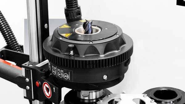
A thermosetting toolholder is a high-precision toolholder system that uses the principle of thermal expansion and contraction to clamp cutting tools. Its main features include high precision , high rigidity , good dynamic balance , stable clamping , and a compact structure . When clamping a tool, a thermosetting machine is used to heat the toolholder. After the toolholder end expands due to heat, the tool is quickly inserted into the expanded toolholder hole. After the toolholder cools, the hole shrinks and tightly clamps the tool, completing the installation. This type of toolholder is commonly used in mold manufacturing, aerospace, and automotive manufacturing.
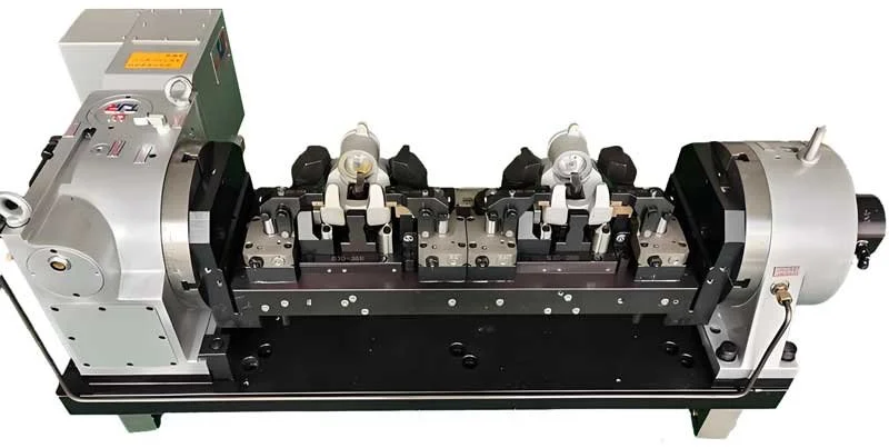
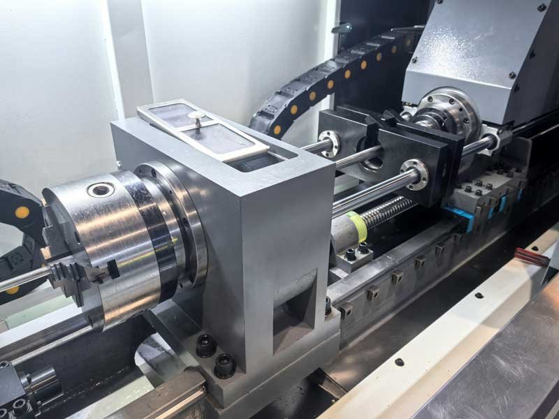
Applications of VMC 4th axis bridge broad
The 4th axis bridge broad generally refers to a machine tool accessory or structural support assembly used to mount a 4th axis (rotary axis), thereby expanding a three-axis machining center to 4th axis machining capability. The bridge plate can also be understood as a mounting platform connecting the four axes to the 4th axis tailstock, providing ample fixture expansion capabilities for the four axes.

Plug and Play first Step: Voltage Adaptation and Electrical Protection
At Smartlathe, we never stop improving. Every innovation begins with one simple question: How can we help our customers use Smartlathe machines more easily and safely—anywhere in the world?
What is Fixed Guide Bush
The Fixed Guide Bush, also known as the steady rest or follow rest, is an auxiliary support device installed on the bed guide rail. It plays a role in preventing vibration, bending and jumping in the processing of slender workpieces. It is especially indispensable when processing long shafts or slender parts.

Types and applications of macro programs
Macro Program or User Macro in CNC system is a powerful function that allows users to use programming structures such as variables, arithmetic and logical operations, conditional branches (IF...THEN...ELSE), loops (WHILE...DO...END) to write more flexible, more general and parameterizable machining programs.
Turn Your Drawings into Solutions: SmartLathe Recommends the Ideal Machine
In actual production, customers often encounter such difficulties: "Get the drawings, but are not sure which machine tool to choose to complete the processing." SmartLathe knows this pain point well. We have a team of experienced engineers that can quickly analyze structural characteristics, material requirements and accuracy tolerances based on customer-provided parts drawings. Through professional process evaluation, we will clarify: what are the difficulties in processing workpieces; whether they need high-speed cutting or high-rigid cutting; whether they involve milling, tapping, turning and milling composite, or heart-wrenching processing; batch size and whether they are suitable for introduction of automation. Based on these analyses, we will recommend the most suitable model for our customers
Application of Reaming
A reamer is a finishing tool used for hole processing. It is mainly used to precisely trim the inner holes that have been pre-drilled, bored or punched to improve the hole's dimensional accuracy, geometric shape accuracy (such as roundness, cylindricity) and surface finish. It is one of the core tools for high-precision hole processing in mechanical manufacturing.
Spindle speed floating function SSV
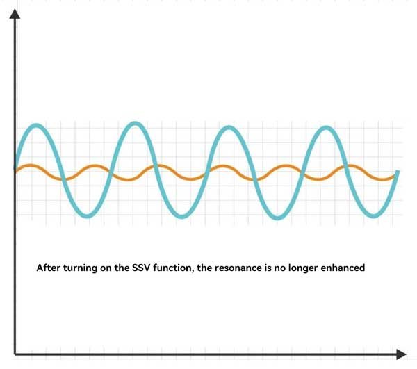
In the application of CNC lathes, the spindle speed variation (SSV) function effectively breaks the resonance frequency during the processing, reduces chattering, and improves processing stability by introducing small periodic fluctuations around the spindle speed. Based on the set speed, the system makes the spindle speed fluctuate periodically within a small range instead of maintaining a constant speed.

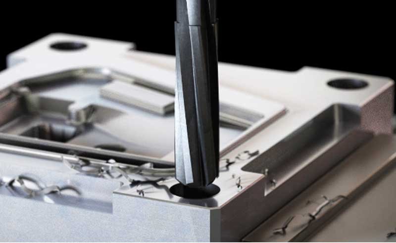
How to Select Appropriate Machining Parameters for Deep Hole Drilling
Deep hole drilling refers to a drilling technique where the depth-to-diameter ratio of the hole exceeds 10:1. This process places higher demands on tool structure, chip evacuation capability, coolant and lubrication systems, as well as machine rigidity. To ensure smooth chip removal and thermal stability during prolonged drilling operations, deep hole drilling commonly utilizes a high-pressure internal coolant system, which provides effective cooling and chip evacuation at the cutting zone.

G72 radial roughing dynamic machining
G72 is a rough turning cycle command in CNC lathes, mainly used to automatically complete rough machining of external circles or end faces. Different from programming by cut, G72 can generate multiple tool paths at one time by setting cutting areas and parameters, realizing intelligent machining of "automatic layering and automatic feed".
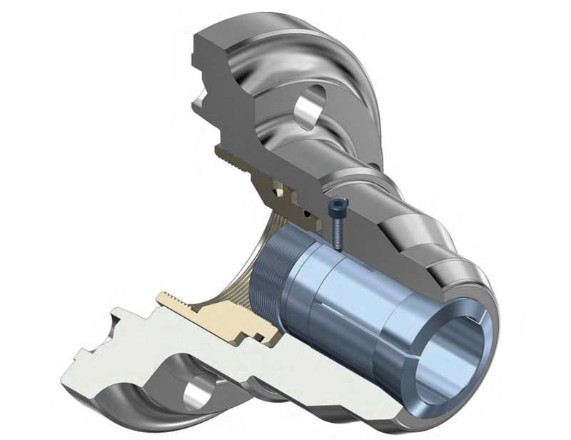
What is 5C and 16C collet?
5C and 16C are two classic American standard collet system models, designed by Hardinge Inc. in the United States and widely used in various precision turning equipment worldwide. They are precision fixtures used to hold cylindrical workpieces, relying on elastic deformation to generate clamping force, featuring high accuracy, stable clamping, and suitability for high-speed machining.
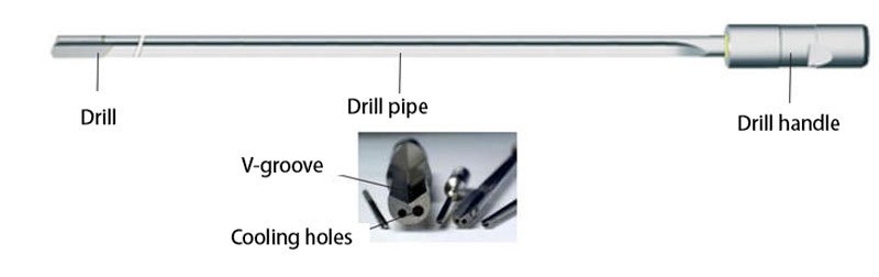
What is a gun drill
Gun drill is a special tool for small diameter deep hole processing, usually used for drilling holes with a diameter of 1mm-30mm and a depth-to-diameter ratio of up to 100:1 or more. Gun drill adopts a single-edge design, coolant enters through the center hole of the drill bit, and chips are discharged along the outer groove of the drill body, ensuring high-precision and efficient processing.
Causes and countermeasures of machining vibration problems
In CNC milling, vibration may occur due to the limitations of cutting tools, tool holders, machine tools, workpieces or fixtures, which will have a certain adverse effect on machining accuracy, surface quality and machining efficiency. To reduce cutting vibration, relevant factors need to be considered. The following is a comprehensive summary for your reference .
Differences in programming between Fanuc and GSK
Both systems support ISO standard G-codes such as G01, G02, G03, etc. The basic programming logic is similar.
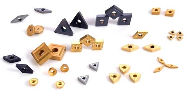
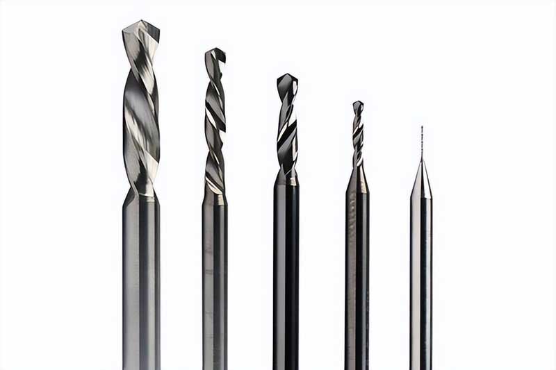
CNC Tool Classification
In modern manufacturing, CNC lathes have become indispensable processing equipment. As the "teeth" of CNC lathes, tools play a crucial role in determining machining efficiency and product quality. This article will help you understand the classification and characteristics of CNC lathe tools, enabling you to select the most suitable tools for your production needs.
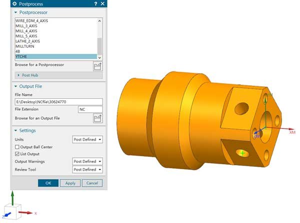
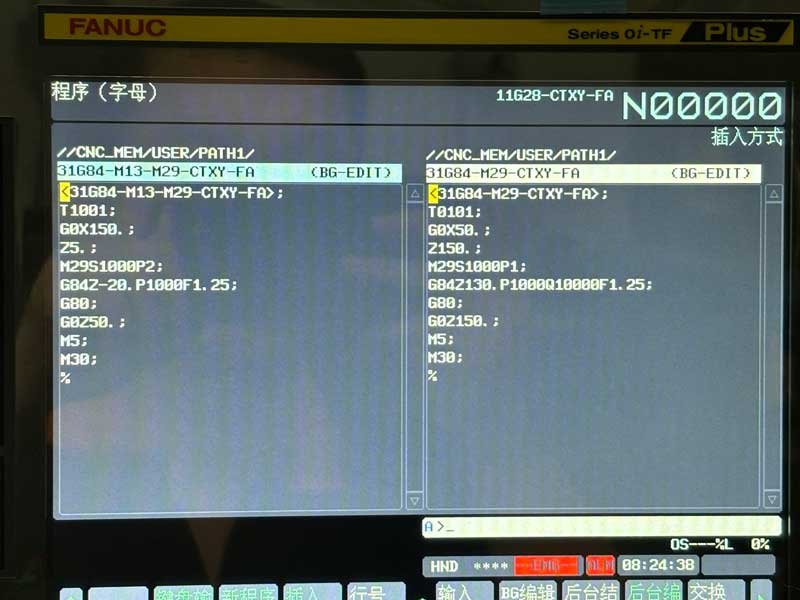
NX post-processing import and machine head connection settings
NX post-processing import and machine head connection settings
What is Deep Hole Drilling?
A deep hole is defined by its depth-to-diameter ratio (D:d), and typically holes greater than 10:1 are considered deep holes. Deep hole machining is widely used in manufacturing industries such as aerospace, automotive, mold, and energy.
The influence of drill bit geometry on drilling
As the most commonly used cutting tool in the machining process, the drill bit's geometry directly affects the drilling efficiency, hole diameter accuracy, surface roughness, and the durability and life of the drill bit. In the drill bit geometry design, the top angle, helix angle, core thickness, chisel edge shape, edge modification, and surface coating are key parameters.
Nickel Alloy Machining Methods
Nickel alloy is a kind of metal material with nickel (Ni) as the main component and other metal elements (such as chromium, iron, molybdenum, copper, aluminum, titanium, etc.) added to improve specific properties. Due to its excellent corrosion resistance, high temperature strength and oxidation resistance, nickel alloy is widely used in aerospace, nuclear energy, marine engineering, petrochemical, medical equipment and other fields.
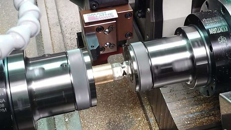
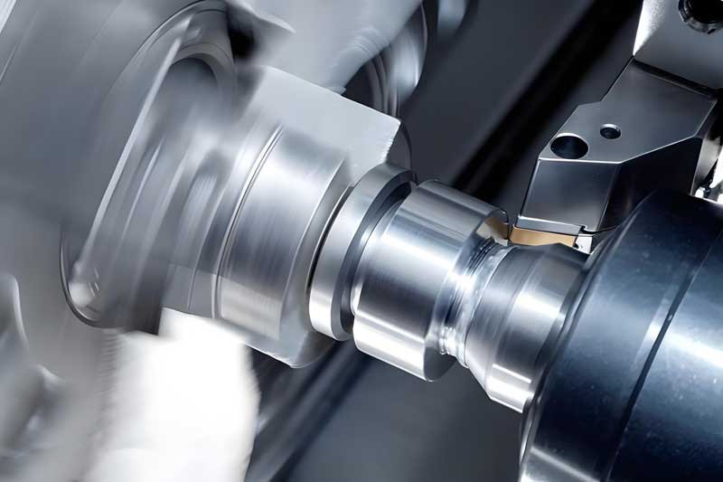
How to use a double-spindle lathe for polygonal butt jointing?
In modern precision machining, dual-spindle machines have become the industry focus due to their unique design and efficient machining capabilities. Multi-polygon alignment, as an emerging machining technique, demonstrates exceptional processing efficiency and product quality with the support of dual-spindle machines. This article will explore the technical features of dual-spindle multi-polygon alignment solutions and their advantages in practical applications.