Geometric Accuracy of CNC Lathe
1. Straightness of the Bed Guide Rails
The straightness of the bed guide rails in the vertical plane after leveling the longitudinal guide rails.
Inspection Tool: Precision spirit level.
Inspection Method: Place the spirit level along the Z-axis on the carriage. Inspect at various positions along the entire length of the guide rail at equal intervals. Record the readings of the spirit level and document them in a report. Use the graphical method to calculate the straightness error of the bed guide rails in the vertical plane. The inspection schematic is as shown in the diagram.
2. Parallelism of the Bed Guide Rails
The parallelism of the bed guide rails after leveling the transverse guide rails.
Inspection Tool: Precision spirit level.
Inspection Method: Place the spirit level along the X-axis on the carriage. Move the carriage along the guide rails and record the readings of the spirit level. The maximum value of these readings is the parallelism error of the bed guide rails. The inspection schematic is as shown in the diagram.
3. Spindle Runout
Inspection Tool: Dial indicator and specialized fixture.
Inspection Method: Apply force 𝐹 (where 𝐹 is the minimum value to eliminate axial clearance) along the spindle axis using a specialized fixture. Mount the dial indicator on a fixed part of the machine. Position the dial indicator probe to touch the steel ball of the specialized fixture and the spindle shoulder support surface along the spindle axis. Rotate the spindle and measure the maximum difference in the dial indicator readings, which represents the axial movement error of the spindle and the axial runout error of the spindle shoulder support surface. The inspection schematic is as shown in the diagram.
4. Radial Runout of the Spindle Centering Journal
Inspection Tool: Dial indicator.
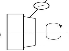
Inspection Method: Mount the dial indicator on a fixed part of the machine. Position the dial indicator probe perpendicular to and in contact with the spindle centering journal. Rotate the spindle and measure the maximum difference in the dial indicator readings, which represents the radial runout error of the spindle centering journal. The inspection schematic is as shown in the diagram.
5. Radial Runout of the Spindle Taper Bore Axis
Inspection Tool: Dial indicator and test bar.
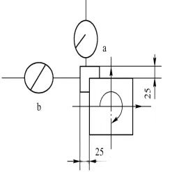
Inspection Method: Insert the test bar into the spindle taper bore. Mount the dial indicator on a fixed part of the machine. Position the dial indicator probe perpendicular to the surface being measured. Rotate the spindle and record the maximum difference in the dial indicator readings, taking measurements at positions a and b as shown in Figure 7-7. Mark the relative circumferential position of the test bar to the spindle. Remove the test bar and reinsert it into the spindle taper bore after rotating it by 90°, 180°, and 270° in the same direction. Conduct measurements at each position. The average value of the four measurements represents the radial runout error of the spindle taper bore axis. The inspection schematic is as shown in the diagram.
6. Parallelism of the Spindle Axis (Relative to Carriage Movement)
Inspection Tool: Dial indicator and test bar.
Inspection Method: Insert the test bar into the spindle taper bore. Mount the dial indicator on the carriage (or tool post). Then:
6.1 Position the dial indicator probes perpendicular to the plane of the test bar's surface. Move the carriage and record the maximum difference in the dial indicator readings and the direction. Rotate the spindle by 180° and repeat the measurement. The arithmetic mean of the two readings is the parallelism error of the spindle axis relative to the carriage movement in the vertical plane.
6.2 Position the dial indicator probes perpendicular to the test bar's surface in the horizontal plane. Repeat the measurement as described in step 1 to obtain the parallelism error of the spindle axis relative to the carriage movement in the horizontal plane.
The inspection schematic is as shown in the diagram.
7. Perpendicularity of the Tool Post's Transverse Movement to the Spindle Axis
Inspection Tool: Dial indicator, disk, and straightedge.
Inspection Method: Mount the disk in the spindle taper bore and the dial indicator on the tool post. Position the dial indicator probe perpendicular to the surface of the disk in the horizontal plane. Move the tool post along the X-axis and record the maximum difference in the dial indicator readings and the direction. Rotate the disk by 180° and repeat the measurement. The arithmetic mean of the two readings is the perpendicularity error of the tool post's transverse movement to the spindle axis. The inspection schematic is as shown in the diagram.
8. Repeatability of Tool Post Indexing and X-axis Directional Indexing Repeatability
Inspection Tool: Dial indicator and test bar.
Inspection Method: Mount the dial indicator on a fixed part of the machine, with the dial indicator probe perpendicular to the surface of the test piece. At the center stroke of the rotary tool post, record the reading. Using an automatic cycle program, retract the tool post, rotate it 360°, and return it to the original position. Record the new reading. The error is calculated as the difference between the maximum and minimum readings over at least three full rotations of the rotary tool post. This inspection should be repeated for each position of the rotary tool post, and the dial indicator should be zeroed for each position. The inspection schematic is as shown in the diagram.


