Principles for Selecting Cutting Tools
1. Tool Selection During Machining
Any time a tool stops working, production halts. However, not all tools have the same level of importance. The tool that is used for the longest cutting duration has a greater impact on the production cycle, so its performance should be prioritized under equal conditions. Special attention should also be given to tools used for processing key components and those with the strictest tolerance requirements. Additionally, tools with poor chip control, such as drills, grooving tools, and threading tools, should be closely monitored because poor chip control can cause tool wear or machine downtime.
|
ISO Standard |
Material |
Condition |
Cutting Speed m/min |
||||
|
BXC |
BMK |
||||||
P |
Non-Alloy steel and cast steel, free cutting steel |
<0.25%C |
Annealed |
25-50 |
30-60 |
||
|
≥0.25%C |
Annealed |
||||||
|
< 0.55%C |
Quenched & tempered |
||||||
|
≥0.55%C |
Annealed |
||||||
|
|
Quenched & tempered |
||||||
|
Low alloy steel and cast steel (less than 5% alloying elements) |
Annealed |
20-25 |
24-30 |
||||
|
Quenched & tempered |
|||||||
|
High alloy steel, cast steel, and tool steel |
Annealed |
18-20 |
22-24 |
||||
|
Quenched & tempered |
|||||||
M |
Stainless steel and cast steel |
Ferritic/martensitic |
25-30 |
30-42 |
|||
|
Martensitic |
|||||||
|
Austenitic |
|||||||
K |
Cast iron nodular (GGG) |
Ferritic/pearlitic |
17-23 |
20-28 |
|||
|
Pearlitic |
|||||||
|
Grey cast iron (GG) |
Ferritic |
||||||
|
Pearlitic |
|||||||
|
Malleable cast iron |
Ferritic |
||||||
|
Pearlitic |
|||||||
N |
Aluminum-wrought alloy |
Not curable |
50-70 |
60-84 |
|||
|
Cured |
|||||||
|
Aluminum-cast, alloyed |
<=12% Si |
Not curable |
30-40 |
36-48 |
|||
|
|
Cured |
||||||
|
>12% Si |
High temperature |
||||||
|
Copper alloys |
>1% Pb |
Free cutting |
22-25 |
24-30 |
|||
|
|
Brass |
||||||
|
|
Electrolytic copper |
||||||
|
Non metallic |
Duro plastics, fiber plastics |
35-45 |
|
||||
|
Hard rubber |
|||||||
S |
High temp. alloys, Super S alloys |
Fe based |
Annealed |
15-20 |
18-24 |
||
|
Cured |
|||||||
|
Ni or Co based |
Annealed |
||||||
|
Cured |
|||||||
|
Cast |
|||||||
|
Titanium alloys |
Alpha + beta alloys cured |
12-18 |
15-20 |
||||
H |
Hardened steel |
Hardened 45-50 HRc |
15-20 |
18-24 |
|||
|
Hardened 51-55 HRc |
|||||||
|
Hardened 56-62 HRc |
|||||||
|
Chilled cast iron |
cast |
10-14 |
12-16 |
||||
|
Cast iron |
Hardened |
8-12 |
10-14 |
||||
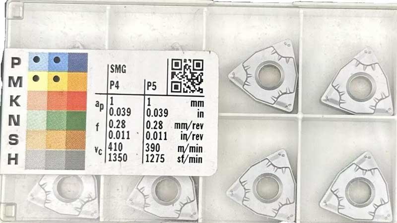
As shown in Figure , the black dots indicate the materials best suited for processing. Almost every insert box features these markings, which should guide your choice of inserts according to the material of the workpiece.
2. Tools Should Match the Machine
Tools are categorized as right-hand or left-hand, making it crucial to select the correct one. Typically, right-hand tools are suitable for counterclockwise (CCW) rotating machines (viewed along the spindle axis), while left-hand tools are for clockwise (CW) rotating machines. If you have multiple lathes, some holding left-hand tools and others compatible with both, opt for left-hand tools. For milling, people usually prefer more versatile tools. However, although such tools cover a broader range of machining tasks, they immediately reduce tool rigidity, increase deflection, lower cutting parameters, and make machining more prone to vibration. Additionally, the size and weight of the tools must align with the tool-changing manipulator of the machine. If you have a machine with a spindle featuring through-coolant holes, choose tools with through-coolant capabilities.
Note: Determining Left-Handed or Right-Handed Tools
Type A: Round-Shank Tools (Rotating Tools)
When viewed from the shank side, if the cutting edge is on the left, it is a left-hand tool; if the cutting edge is on the right, it is a right-hand tool.
Type B: Non-Rotating Tools (e.g., Turning Inserts)
When the cutting tip faces you, if the cutting edge is on the left, it is a left-hand tool; if the cutting edge is on the right, it is a right-hand tool.
3. Tool Specification Selection
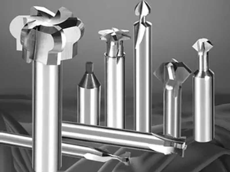
End mills are used for machining flat and curved surfaces. Common types include end mills, face mills, and ball nose mills. Tool specifications are generally expressed by shank diameter, cutting length, and cutting diameter. Common shank diameters include 10, 12, 16, and 20 mm, while cutting length and diameter are determined based on processing needs.
Turning tools are used for machining external cylindrical surfaces. Common types include internal and external turning tools, and thread-cutting tools. Specifications for turning tools typically include shank diameter, cutting width, and cutting depth.
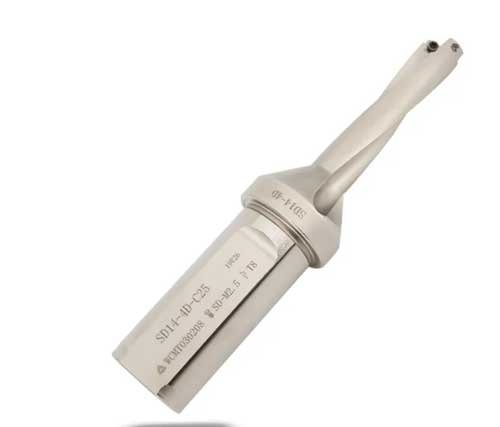
Drill sizes can be expressed by diameter, overall length, and working length. Common diameters include 0.5, 1, 2, 3, 4, 5, 6, 8, and 10 mm. Working length is typically three times the diameter, while overall length is about five times the diameter.
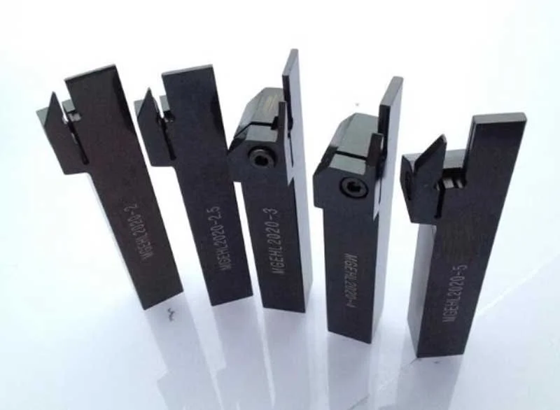
Grooving tool specifications are usually defined by shank diameter, cutting width, and cutting depth. Common shank diameters include 10, 12, 16, and 20 mm, with cutting width and depth based on processing needs.
4. Choosing Replaceable Insert or Replaceable Head Tools
The guiding principle here is simple: avoid sharpening tools whenever possible. Except for a few drills and face mills, always opt for tools with replaceable inserts or heads if possible. This will save you labor costs and ensure consistent machining results.
5. Tool Material and Grade
The choice of tool material and grade is closely related to the properties of the workpiece material, as well as the machine’s maximum speed and feed rate. For most materials, a coated alloy grade is usually the best choice. Always refer to the “Grade Application Recommendation Chart” provided by your tool supplier. A common mistake is trying to solve tool life issues by switching to a similar grade from a different manufacturer. If the current tool is underperforming, switching to a similar grade is unlikely to yield different results. To solve the issue, you must first identify the cause of tool failure.
6. Machine Power Requirements for Tools
For example, if you have a lathe with a 6 kW power rating, you should choose tools and machining parameters that allow you to use up to 80% of the machine’s power, provided the workpiece and fixture permit it. Pay close attention to the power and speed charts in the machine’s user manual, and select tools that allow you to achieve optimal cutting performance within the effective power range of the machine.
7. Number of Cutting Edges
The principle is “the more, the better.” Purchasing a tool with twice the number of cutting edges does not mean paying twice the price. Over the past decade, advancements have led to turning tools, grooving tools, parting tools, and some milling inserts doubling the number of cutting edges. For example, it is not uncommon to replace a milling cutter with a four-edge insert with one that has sixteen cutting edges. Increasing the number of effective cutting edges directly impacts feed rates and productivity.
8. Choosing Solid or Modular Tools
Small-sized tools are more suitable for solid designs, while large-sized tools are better suited for modular designs. For large-sized tools, when a tool fails, users often prefer to replace only the small, inexpensive parts to restore the tool.
Solid tools are typically made of carbon tool steel, alloy tool steel, and high-speed steel. These tools are easy to manufacture, and even when dull, they can be resharpened multiple times, making them relatively low-cost. Solid tools are suitable for single-piece production on standard lathes, particularly in environments where low cost and high efficiency are required.
Modular tools are designed for easy disassembly and replacement of inserts and tool bodies. This design improves work efficiency and reduces costs. Modular tools reduce cutting load on the tool body, extend tool life, and reduce tool consumption costs, making them widely applicable in industrial production.
9. Choosing Single-Purpose or Multifunctional Tools
Composite tools can combine drilling, turning, internal machining, threading, and chamfering. The more complex the workpiece, the more suitable it is for multifunctional tools.
This multifunctional tool is capable of performing drilling, turning, and boring operations all in one.
10. Choosing Standard or Custom Tools
With the widespread adoption of CNC machining centers, it is generally believed that workpiece shapes can be achieved through programming, eliminating the need for custom tools. However, custom tools still account for 15% of total tool sales. Why? Special tools can meet precise workpiece size requirements, reduce operations, and shorten processing cycles. For mass production, custom tools can significantly reduce processing time and costs.
11. Chip Control
Remember, your goal is to machine the workpiece, not the chips, but the chips can clearly reflect the cutting state of the tool. Generally speaking, people have biases against chips, as most have not been trained to interpret them. Keep the following principle in mind: good chips will not interfere with machining, while bad chips will do the opposite.
All inserts are designed with chip breakers, which are tailored according to the feed rate, whether it's for light finishing cuts or heavy roughing.
The smaller the chips, the harder they are to break. For difficult-to-machine materials, chip control becomes a significant challenge. Although you cannot change the material being machined, you can optimize the tool by adjusting cutting speed, feed rate, depth of cut, and the nose radius of the tool. Optimizing chips and machining is a result of a comprehensive selection process.
Traditional chip breaker grooves can be categorized into three types: A -linear arc type, B - linear type, and C - arc type, as shown in FJG.11.2.
12. Programming
When faced with tools, workpieces, and CNC machines, it is essential to define the tool path. Ideally, you should understand basic machine codes and have advanced CAM software. Tool paths must consider tool characteristics such as milling angle, rotation direction, feed, and cutting speed. Each tool has corresponding programming techniques to shorten machining cycles, improve chip control, and reduce cutting forces. A good CAM package can save labor and enhance productivity.
13. Choosing Innovative or Conventional Tools
With the rapid advancement of technology, cutting tool productivity doubles every ten years. Comparing the recommended cutting parameters from a decade ago with today's tools, you’ll find that modern tools can double machining efficiency while reducing cutting power by 30%. New tool materials are stronger, tougher, and capable of higher cutting speeds with lower cutting forces. Innovations in chip breaker design and grade application have increased versatility, while modern tools also offer more multifunctionality and modularity, reducing inventory and expanding tool applications. These advancements drive new product designs and machining concepts, such as combined turning and grooving tools, high-feed milling cutters, and techniques like high-speed machining, minimum quantity lubrication (MQL), and hard turning. Based on these and other factors, it is essential to stay up-to-date with the latest advanced tool technologies to avoid falling behind.
14. Price
While tool cost is important, the production cost associated with the tool is even more crucial. Although tools have their price, their true value lies in their role in productivity. Typically, the cheapest tools result in the highest production costs. Cutting tools account for only 3% of the part cost, so focus on tool productivity, not just the purchase price.


