What is capto tool holder?
1. Definition
Capto is a double-sided locating hollow tapered tool holder, available in seven models: C3, C4, C5, C6, C8, C8x, and C100, each corresponding to a different diameter. The cross-section of the Capto tool holder features three evenly spaced curved surfaces, with three convex edges distributed uniformly at 120° intervals around the circumference. This design maximizes contact surface area, minimizes stress concentration, reduces deformation and wear, ensures more even force distribution, allows for greater torque transmission, and enhances precision in positioning.
2.The structure of Capto tool holder
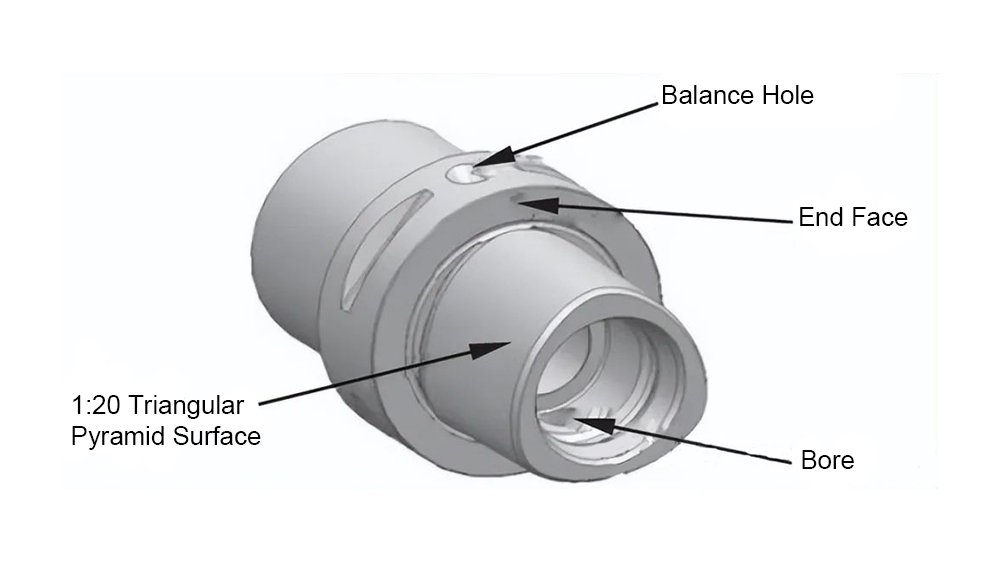
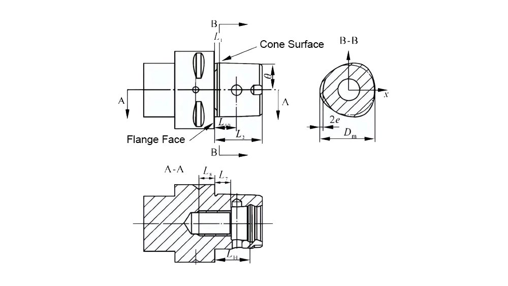
The Capto tool holder features a triangular pyramid structure, as depicted in the diagram below. Its three convex edges are evenly distributed around the circumference, connected by arcs in between. The taper ratio of the holder is 1:20. When fitted into the spindle, the hollow tapered shank automatically centers itself within the spindle taper hole. The Capto tool holder is mounted onto the spindle bore, with a 0.2mm gap between the flange face of the holder and the spindle end face before the drawbar is tightened. Under the tightening force, the hollow tapered shank undergoes elastic deformation, ensuring tight contact between the flange face of the holder and the spindle end face, thus achieving simultaneous clamping and positioning of both the tapered surface and end face.
3.The features of Capto tool holder
Compared to HSK tool holders, the main feature of Capto tool holders lies in their cross-section, which consists of three evenly spaced curved surfaces. The unique triangular pyramid structure enables torque transmission without slippage in two directions.
The shape of the B-B interface in the above diagram is defined by the following equation:
As Dm varies, the changes in the cross-sectional shape of the tool holder are depicted in the above diagram. It can be observed that as Dm increases, the dimensions of the cross-section uniformly increase. If the size of the spindle bore remains constant, the interference fit between the tool holder and the spindle increases. This results in improved connection stiffness and radial positioning accuracy in the Capto tool system. Conversely, when Dm decreases, the dimensions of the cross-section uniformly decrease. As a consequence, the interference fit between the tool holder and the spindle diminishes, potentially leading to clearance. This reduction in contact area of the tapered surface weakens the radial positioning effect, eventually leading to its loss.
From the diagram, it's evident that as e increases, the dimensions at the three convex edges become larger, taking on a sharper shape, while the dimensions at the transition points between the edges decrease. Consequently, when the tool holder is fitted onto the spindle, there is increased interference at the convex edges but decreased interference or even clearance at the transition points between the edges. Conversely, when e decreases, the dimensions at the convex edges decrease while those at the transition points increase. In both scenarios, there is interference between the tool holder and the spindle, which doesn't significantly affect the radial positioning accuracy and connection stiffness of the Capto tool system. However, uneven interference can accelerate wear on the tool holder.


