Classification of geometric tolerances during CNC lathe machining—Guide rails
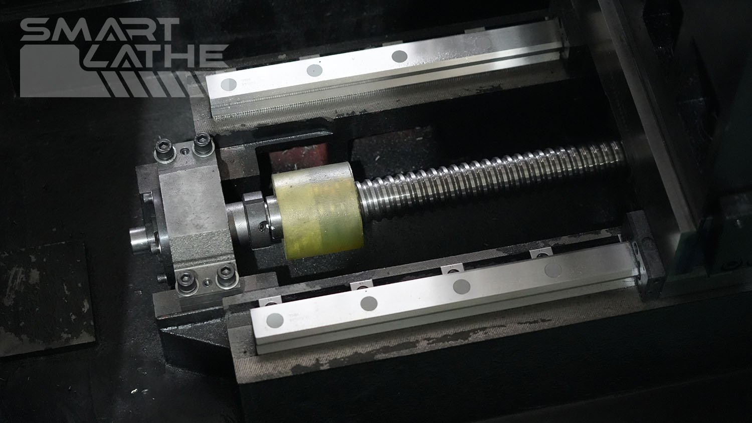
The geometric tolerances of CNC lathe guide rails have a significant impact on machining accuracy and workpiece quality. These tolerances mainly include horizontal straightness tolerance, vertical straightness tolerance, and parallelism tolerance of the guide rails.
Horizontal Straightness
The horizontal straightness tolerance of CNC lathe guide rails refers to the deviation of the guide rail in the horizontal direction. It indicates the maximum deviation between the actual path of the guide rail in the horizontal plane and the ideal straight line.
Vertical Straightness
The vertical straightness tolerance of CNC lathe guide rails refers to the deviation of the guide rail in the vertical direction. It represents the maximum deviation between the actual path of the guide rail in the vertical plane and the ideal straight line.
Parallelism Tolerance Between Front and Rear Guide Rails
The parallelism tolerance of CNC lathe guide rails refers to the parallel deviation between two guide rails or between a guide rail and other reference surfaces. It indicates the maximum deviation between the actual parallelism and the ideal parallelism of two guide rails or a guide rail and a reference surface.
Measurement Methods for Geometric Tolerances of Guide Rails
Depending on the type of tolerance, measurement methods include those for straightness tolerance and parallelism tolerance:
Measurement Methods for Straightness Tolerance
Using a level: Place the level on the guide rail, move along the direction of the rail, and record changes in the level readings.
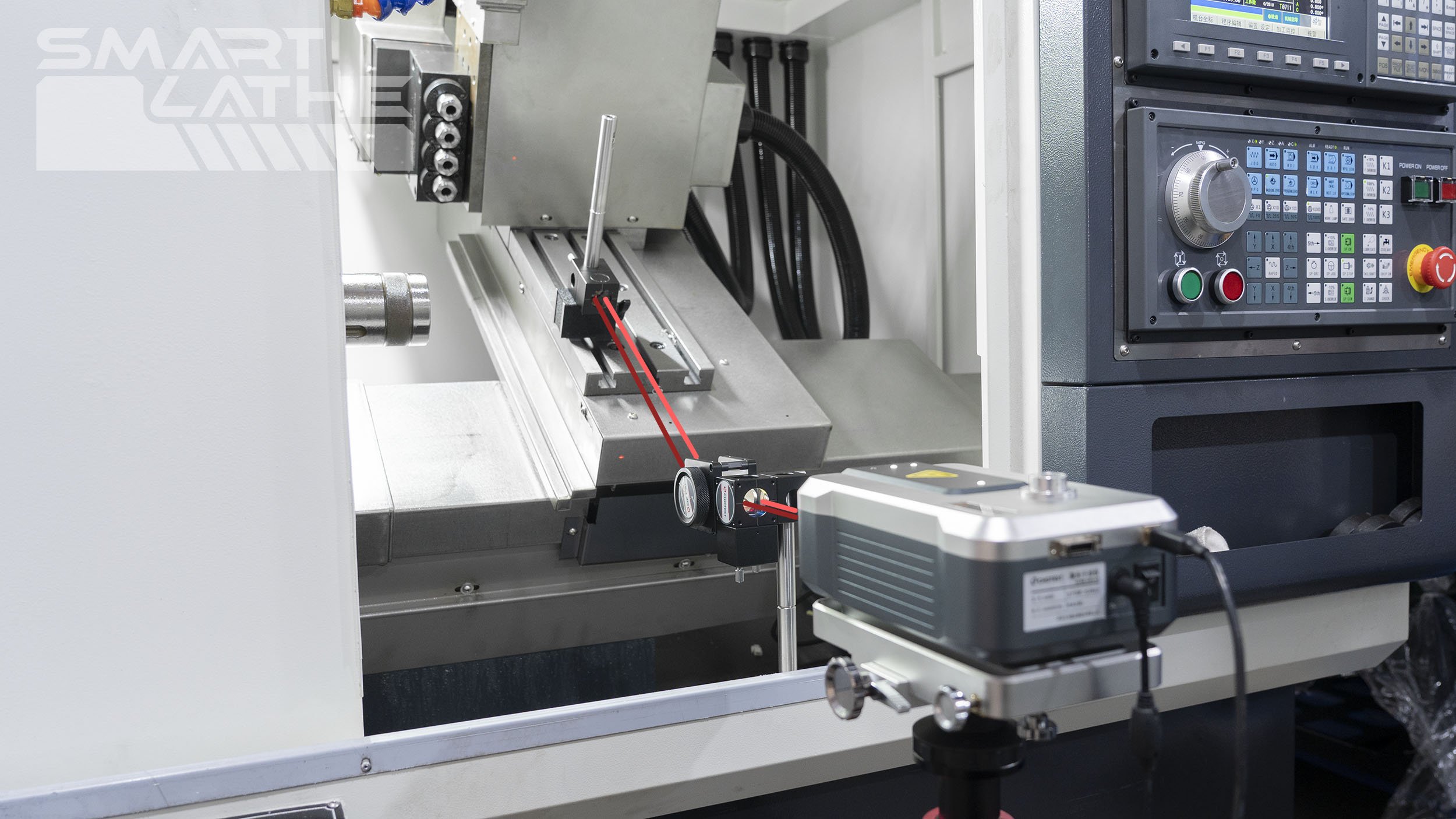
Laser interferometer: Utilize a laser interferometer to emit laser beams along the guide rail direction and measure deviations in the laser path to determine straightness tolerances.
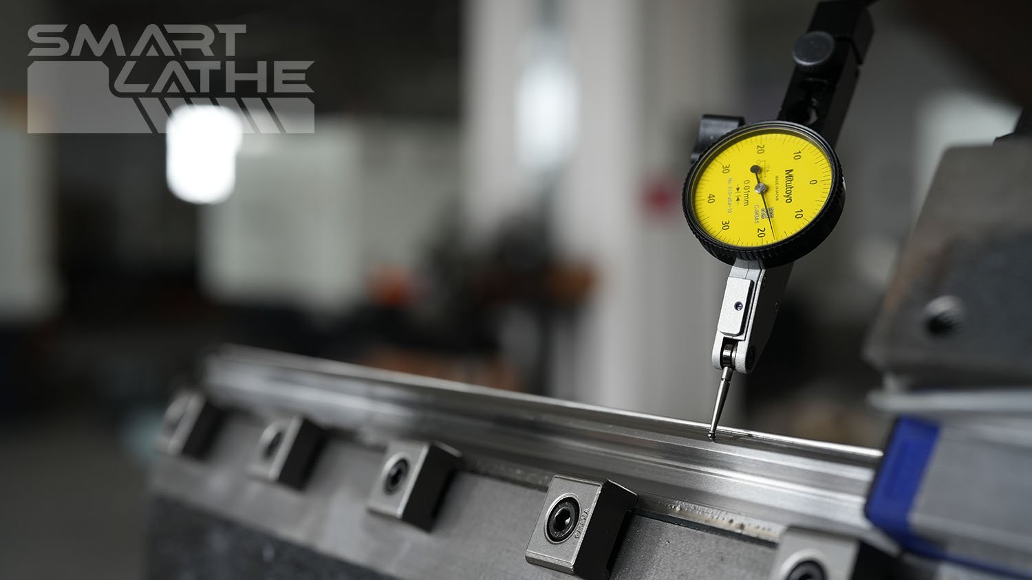
Straightness gauge: Use precision straightness measuring instruments (such as straight edges and dial indicators) to measure section by section along the guide rail and record readings.
Measurement Methods for Parallelism Tolerance
Using a parallelism gauge: Place the parallelism gauge on two guide rails, move along the guide rail direction, and record changes in the gauge readings.
Using precision parallel blocks and dial indicators: Position parallel blocks between two guide rails and use dial indicators to measure changes in distance between the parallel blocks and guide rails.
Laser interferometer: Measure parallelism tolerance between two guide rails or between a guide rail and a reference surface using a laser interferometer.
Factors Influencing CNC Lathe Guide Rail Tolerances During Machining
Effects of CNC Lathe Guide Rail Tolerances During Machining
When the horizontal straightness tolerance of the guide rail is Δy, it causes tolerances in the workpiece's radial dimension as follows:
ΔR=ΔY
If the bed rail has a straightness tolerance in the horizontal plane, it causes the workpiece to produce shape tolerances and size tolerances in the longitudinal and transverse sections, respectively. When the guide rail protrudes backward, the workpiece produces saddle-shaped processing tolerances; when the guide rail protrudes forward, the workpiece produces drum-shaped processing tolerances.
If the bed body guide rail has straightness tolerances in the vertical plane, it will cause the tool tip to produce tangential displacement ΔZ, resulting in an tolerance in the radial direction of the workpiece:
ΔR≈ΔZ²/d
Setting: ΔZ=ΔY=0.01mm, R=50mm, the original machining tolerance caused by the normal direction is ΔR=ΔY=0.01mm, and the original machining tolerance caused by the tangential direction
ΔR≈ΔZ²/d=0.000001mm
This value can be completely ignored. Because the numerical value of ΔZ is very small, this tolerance has little effect on the dimensional accuracy and shape accuracy of the workpiece.
When there is parallelism tolerance (distortion) between the front and rear guide rails of the bed, the carriage of the CNC lathe will deflect when moving along the bed, causing the tool tip to deviate relative to the workpiece, resulting in shape tolerances (drum-shaped, saddle-shaped, taper).
From Figure, it can be seen that the final result of the distortion of the front and rear guide rails of the CNC lathe reflects on the workpiece, thereby generating machining tolerance Δy. From geometric relationships, it can be derived that:
Δy≈H*Δ/B
In general, for the CNC lathe, H≈2B/3, so this original tolerance Δ has a significant impact on machining accuracy.


