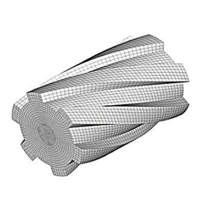
Comparison of Helical Splines and Straight Splines
1. Structural and Design Comparison
1.1 Helical Splines
The spline teeth are helical, similar to threads. The tooth surface is at a helical angle, with a smaller tooth profile angle. The design is more complex, and the manufacturing difficulty is higher.
1.2 Straight Splines
The spline teeth are straight, parallel to the spline axis. The tooth surface is parallel to the axis, with a simple tooth profile. The design is relatively simple, and manufacturing is easier.
2. Load Capacity Comparison
2.1 Helical Splines
Due to the helical shape of the tooth surface, the contact area is large, allowing for even load distribution. Suitable for high-torque, heavy-load applications.
2.2 Straight Splines
The contact area is relatively small, and load distribution is not as uniform as in helical splines. Suitable for general transmission systems and medium-load applications.
Spline shafts are prone to failure under high torque.
When the transmitted torque is too high, a straight-toothed spline shaft may experience torsional failure outside the area near the spline shaft side. This is because the load along the length of the straight spline is theoretically even, but stress concentration occurs at the end of the spline near the shaft side and beyond.
By angling the spline teeth relative to the axis of the shaft, the torsional deformation along the entire spline length becomes more uniform, and contact on the driving tooth side becomes more complete. By distributing the load, the rotational torque is spread over a greater length of the shaft, including the spline length, minimizing stress concentration under high loads. This provides higher load capacity, smoother torque transmission, and better misalignment tolerance.
3. Dynamic Performance Comparison
3.1 Helical Splines
Helical splines offer better smoothness and synchronization during rotation. The helical angle reduces shock loads, improving the smoothness of the transmission system.
3.2 Straight Splines
Straight splines may generate greater vibration and noise during rotation. They experience higher shock loads and have relatively poorer smoothness.
Under load, straight splines deform less and experience higher stress near the shaft side, while deformation is greater and stress is lower away from the shaft side. To achieve more even load distribution on the teeth, the teeth should be inclined opposite to the direction of deformation.
4. Manufacturing and Cost Comparison
4.1 Helical Splines
Manufacturing is complex and costly, requiring precise machining equipment and techniques.
4.2 Straight Splines
Manufacturing is relatively simple and cost-effective. Can be produced with conventional machining equipment.
The choice between helical and straight splines should be based on specific application needs, budget, manufacturing capabilities, and transmission system requirements. If high load capacity and smooth operation are needed, helical splines are the better choice. If cost control is the primary concern, straight splines are more suitable.


