Calculation of Machining Time for Facing, Parting Off, and Deep Grooving on a CNC Lathe
SMARTLATHE often needs to calculate machining times during the analysis of CNC lathe drawings. While CNC programming software can typically complete these calculations quickly, it is important for us to understand how the software performs these calculations.
To calculate the machining time for facing, parting, and deep grooving on a CNC lathe, you need to know some basic parameters, such as cutting speed, feed rate, and cutting depth.
1. Parameters and Definitions
In the calculation process, time is measured in minutes, diameter in millimeters, cutting speed (SFM) in meters per minute, and feed rate in millimeters per revolution.
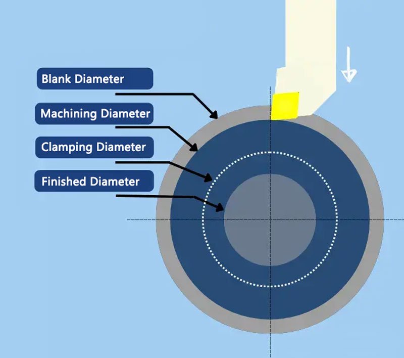
d1 – Initial machining diameter
d2– Final machining diameter
n max– Maximum spindle speed of the machine
V𝑐– Cutting speed
f– Feed rate
dc– Clamping diameter: the diameter at which the maximum spindle speed of the machine limits the cutting speed
t1– Machining time for the diameter larger than the clamping diameter
t2– Machining time for the diameter smaller than the clamping diameter
T– Total cycle time
2. Calculation of Cutting Time
Using the method of controlled variables, we assume the diameter is constant. The operation time for longitudinal turning is straightforward to calculate on CNC lathe. Therefore, during the entire operation, both the cutting speed and spindle speed remain constant, and the following simple formula applies (where l is the distance to be turned):
In facing, parting, and grooving operations, the diameter continuously changes, and the total cutting time should be calculated through integration.
In metric units, the cutting speed is Vc(m/min), while diameter and feed rate are usually in millimeters (mm). Therefore, when using metric units, it is essential to ensure unit consistency. Since each CNC lathe has a maximum spindle speed limit (n max), the situation becomes more complex. To maintain the cutting speed (Vc), the spindle speed (n) will increase as the machine moves from d1 to d2.
At a certain diameter, n will reach n max. This diameter is referred to as the "clamping diameter" (dc), because from this diameter onwards, the spindle speed is "clamped" and the cutting speed begins to decrease.
The first formula t1 applies only to diameters greater than the clamping diameter. For diameters smaller than the clamping diameter, a different and simpler formula is used.
3.Clamping Conditions
To perform the correct calculations, you need to determine the conditions relative to the clamping diameter.
Condition 1: Both the initial machining diameter and the final machining diameter are greater than the clamping diameter.
Condition 2: The clamping diameter lies between the initial machining diameter and the final machining diameter.
Condition 3: Both the initial machining diameter and the final machining diameter are smaller than the clamping diameter.


