Tolerance Compensation for Twin-Spindle CNC Lathe
1. Tolerance Compensation
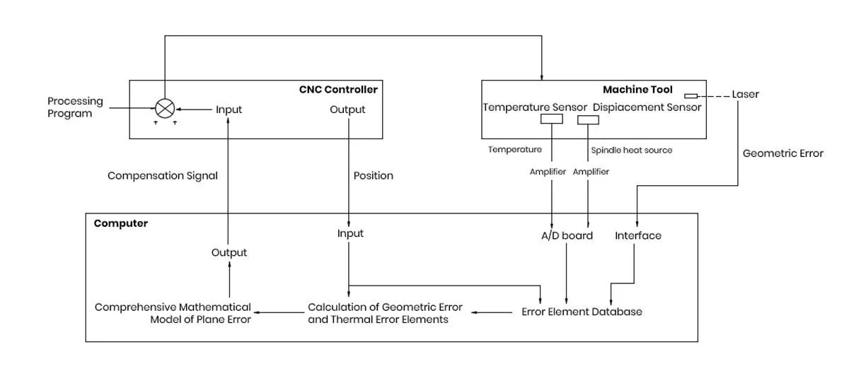
Tolerance compensation is divided into thermal compensation and geometric compensation. The machine tool has a compensation system primarily composed of a microcomputer integrated with the machine tool controller.
The compensation value is calculated by the microcomputer based on the temperature signals from the machine tool and the worktable's motion position signals, combined with the comprehensive Tolerance mathematical model. The value is then sent to the machine tool controller to provide additional feed movement to the tool carriage for real-time compensation.
The main sources of thermal Tolerance in machine tools are the motor, bearings, transmission parts, hydraulic systems, and external and internal heat sources such as environmental temperature. These sources cause thermal deformation in the machine components. These Tolerances can be reduced by improving the machine structure during design and manufacturing. However, in most cases, machine Tolerances cannot be reduced by design and manufacturing techniques alone.
2. Comprehensive Tolerance Calculation Method
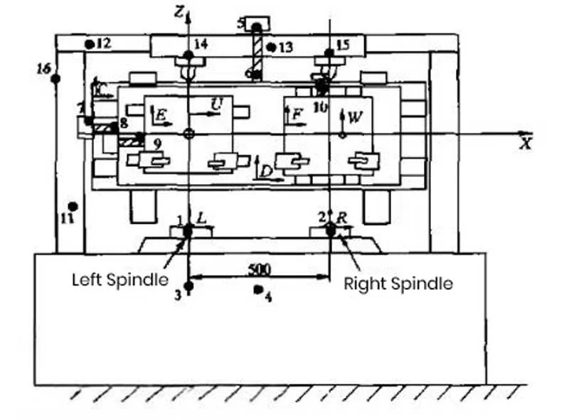
This study involves a machine tool with both left and right spindles, requiring the creation of two separate Tolerance mathematical models. Since the homogeneous coordinate transformation method is used to derive the Tolerance mathematical model, a series of coordinate systems must be established to calculate the Tolerance between the tool tip and the workpiece. The reference coordinate system A is fixed on the machine bed. Coordinate systems O and R are set on the left and right spindles, respectively, and move with their thermal deformations. Coordinate systems C, D, E, and F are set on the large carriage (Z-axis carriage), middle carriage (X-axis carriage), left small carriage (U-axis carriage), and right small carriage (W-axis carriage), respectively, and move with the carriages and their thermal deformations.
The comprehensive Tolerance for each coordinate system is calculated using certain transformation formulas.
The 23 Tolerance elements of geometric and thermal Tolerances can be classified into two categories: position-related Tolerance elements and position-independent Tolerance elements. Laser measuring devices are used to measure position-related Tolerances and perpendicularity, while displacement sensors are used for position-independent Tolerance elements, such as spindle thermal drift and origin thermal drift Tolerances. While measuring these Tolerances, the machine's temperature field and carriage position are recorded. After measurement, Tolerance elements are modeled as functions of the machine position and temperature. Finally, the measured and calculated Tolerance elements are substituted into the comprehensive Tolerance formula.
The machine tool has three groups of position-independent Tolerance elements: perpendicularity, origin thermal drift, and spindle drift, which are computed using the comprehensive Tolerance formula.
3. Compensation System and Results
The compensation control system is composed of a microcomputer integrated with the machine tool controller. Temperature signals related to thermal Tolerances and carriage motion signals related to geometric Tolerances are input into the microcomputer through an A/D board. Based on a pre-input comprehensive Tolerance model, the instantaneous comprehensive Tolerance value is calculated, and the compensation value (the negative of the Tolerance) is sent to the machine tool controller. The controller provides additional feed movement to the tool carriage based on the compensation value to achieve real-time compensation.
4.Tolerance Compensation Validation Method
Real-time Tolerance compensation technology is an effective means to further improve the machining accuracy of CNC machine tools.
The comprehensive Tolerance mathematical model presented includes 23 major Tolerance elements of the machine tool studied, comprising both geometric and thermal Tolerances. Some Tolerance elements are not only functions of temperature but also of position. In most cases, these two factors can be separated.
The method's validity can be verified through cutting tests. After applying compensation, the machine Tolerance is reduced by approximately 75%, significantly improving machining accuracy.


