The Difference Between Positioning Accuracy and Repeatability in CNC Lathes
In CNC lathe operations, positioning accuracy and repeatability are two key parameters that directly affect machining quality and production efficiency. Understanding and correctly applying these concepts can help optimize the machining process and improve product quality. This article will detail these two concepts and their differences.

Selection of Threading Inserts for CNC Lathes
When performing threading on a CNC lathe, it is crucial to select the most suitable threading inserts for your application based on the insert type, flank/radial clearance, and insert profile. These factors significantly impact chip control, insert wear, tool life, and thread quality.

Adiabatic Shearing Phenomenon in High-Speed Cutting
In the field of precision manufacturing, high-speed cutting technology is highly regarded for its efficiency and precision. However, behind this technology lies a complex physical process known as the "adiabatic shearing phenomenon." So, what is the adiabatic shearing phenomenon in high-speed cutting? Today, let's unveil the mystery behind this technology.
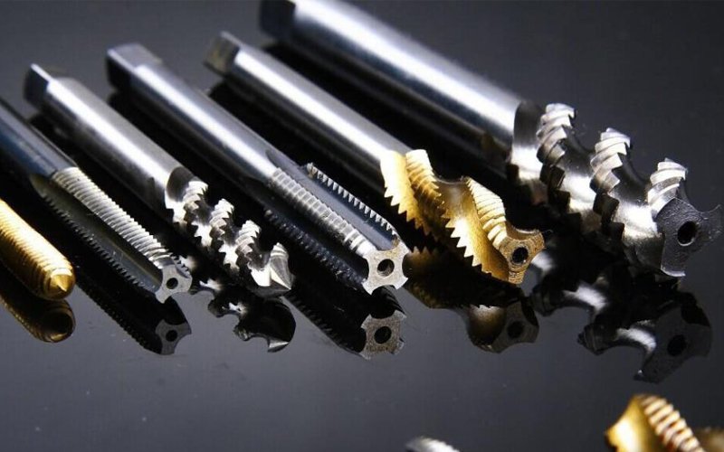
Common issues and solutions for rigid tapping
During the tapping process, various issues can arise that affect production techniques and efficiency. Today, we will analyze the solutions to common tapping problems.
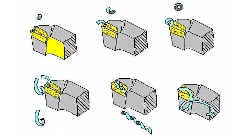
The Impact of Spindle Speed and Feed Rate on Chip Formation
In the world of CNC lathe, chip formation is a crucial indicator. It directly affects machining efficiency, tool life, and the quality of the finished product. When delving into chip formation, two critical factors come to the forefront: spindle speed and feed rate.
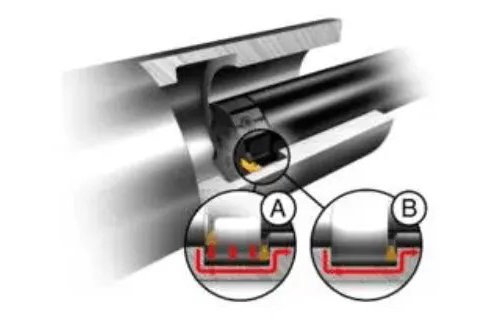
CNC Lathe Internal Grooving Process
The two main challenges in internal groove machining are excessive extension of the guide rod and poor chip removal. Excessive extension can lead to deflection and vibration issues. Vibration and poor chip removal can cause insert breakage. Difficulty in chip removal can also lead to poor surface finish. The most common internal groove machining process is radial grooving; however, multi-groove turning (A) and feed-in turning (B) can also be used.

Common Solutions for Tool Sticking on CNC Lathes for Various Materials
Tool sticking on CNC lathes refers to the phenomenon where the cutting tool adheres to the workpiece material during machining. This results in material buildup on the tool surface, affecting both the quality and efficiency of the machining process. To address this issue, it is essential to understand the properties of the materials and the causes of the phenomenon to provide suitable solutions.
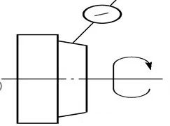
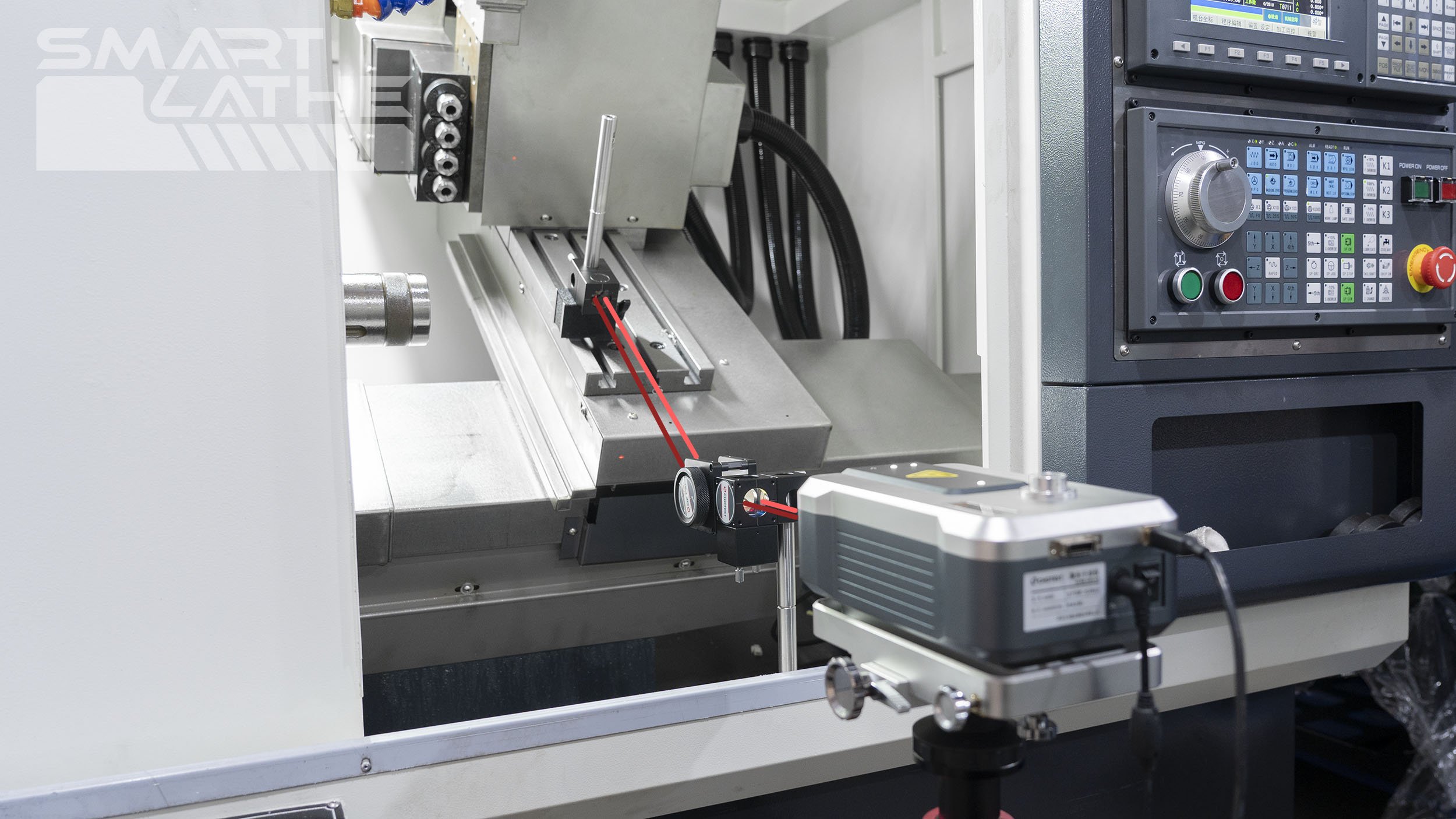
Geometric Accuracy of CNC Lathe
The straightness of the bed guide rails in the vertical plane after leveling the longitudinal guide rails.
Inspection Tool: Precision spirit level.
Inspection Method: Place the spirit level along the Z-axis on the carriage. Inspect at various positions along the entire length of the guide rail at equal intervals. Record the readings of the spirit level and document them in a report. Use the graphical method to calculate the straightness error of the bed guide rails in the vertical plane. The inspection schematic is as shown in the diagram.
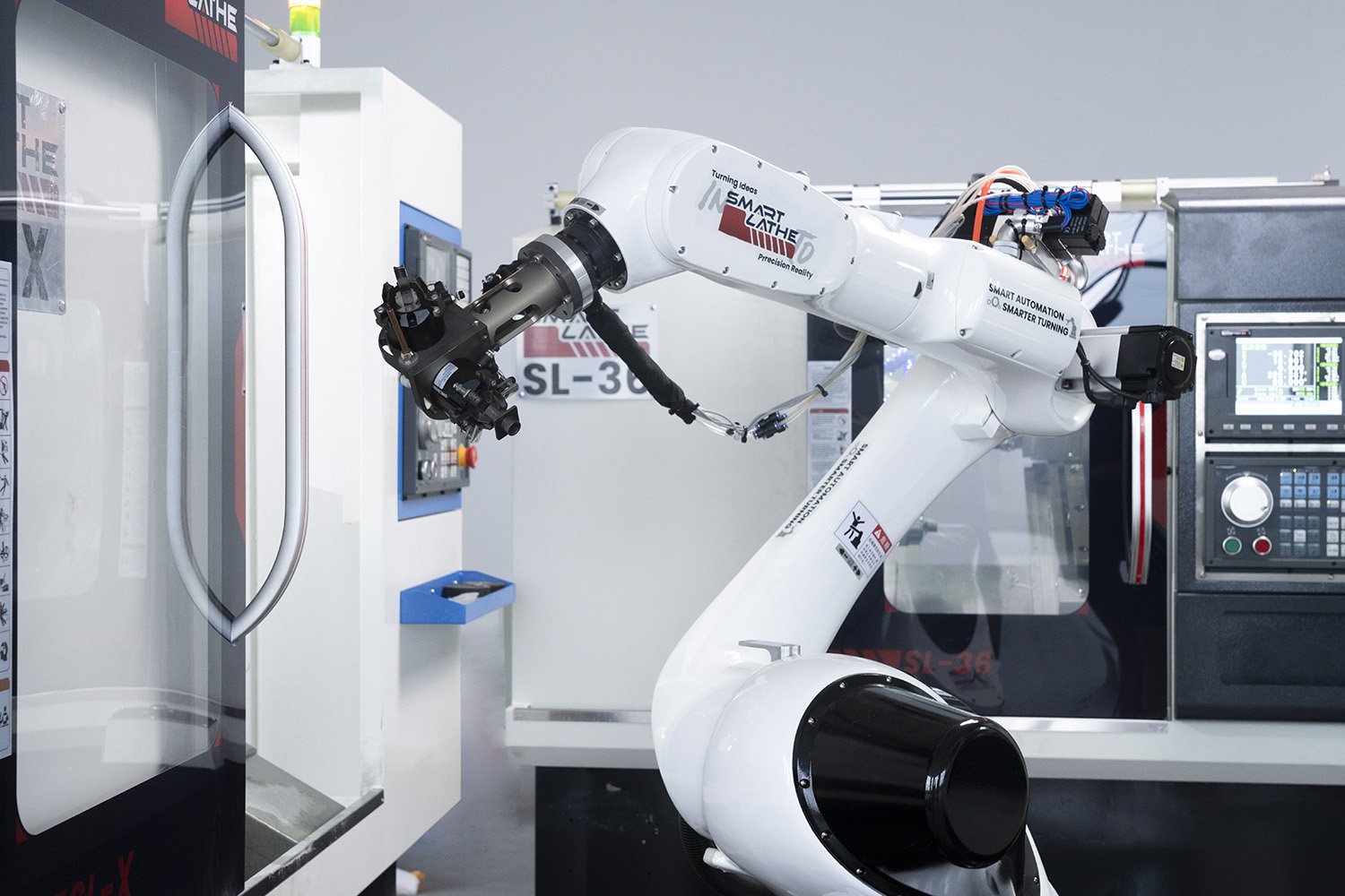
Application of Automated Robotic Arms in CNC Lathes
With the rapid advancement of technology, automation is increasingly being applied in the manufacturing industry. As a crucial component of this trend, the use of automated robotic arms in CNC lathes not only enhances production efficiency but also improves the precision and quality of products. This article will explore the application of automated robotic arms in CNC lathes and the numerous advantages they offer.
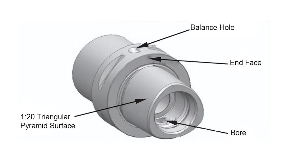
What is capto tool holder?
Capto is a double-sided locating hollow tapered tool holder, available in seven models: C3, C4, C5, C6, C8, C8x, and C100, each corresponding to a different diameter. The cross-section of the Capto tool holder features three evenly spaced curved surfaces, with three convex edges distributed uniformly at 120° intervals around the circumference. This design maximizes contact surface area, minimizes stress concentration, reduces deformation and wear, ensures more even force distribution, allows for greater torque transmission, and enhances precision in positioning.

Common Tolerances on CNC Lathes
Tolerances on CNC lathes refer to the allowable deviation range between the shape and position of the part during the machining process and the design requirements. Tolerances consist of shape tolerances and positional tolerances. Shape tolerances refer to the shape deviations between different parts of the part, such as straightness, roundness, cylindricity, etc. Positional tolerances refer to the positional deviations between different parts of the part, such as parallelism, perpendicularity, coaxiality, etc. CNC lathes achieve high-precision tolerances by controlling tool motion trajectories and machining parameters, ensuring the quality and accuracy of the parts.
Spin Window on CNC Lathes
The introduction of the Spin Window has improved the efficiency and safety of CNC lathes, as well as enhanced the operational efficiency and skill level of operators.
Following a series of technical evaluations, SMARTLATHE has proposed an electrically operated visual observation window solution.

The selection between True Y-axis and Wedge type Y-axis on CNC lathes
In CNC lathes, different machining effects can be achieved by selecting different Y-axis transmission methods, with the Y-axis transmission structure typically adopting two different designs: True Y-axis and wedge type Y-axis. True Y-axis utilizes Y-axis linear interpolation control, while wedge type Y-axis monitors surface contour errors in real-time and compensates by fine-tuning Y-axis movement. They each have their advantages and disadvantages.
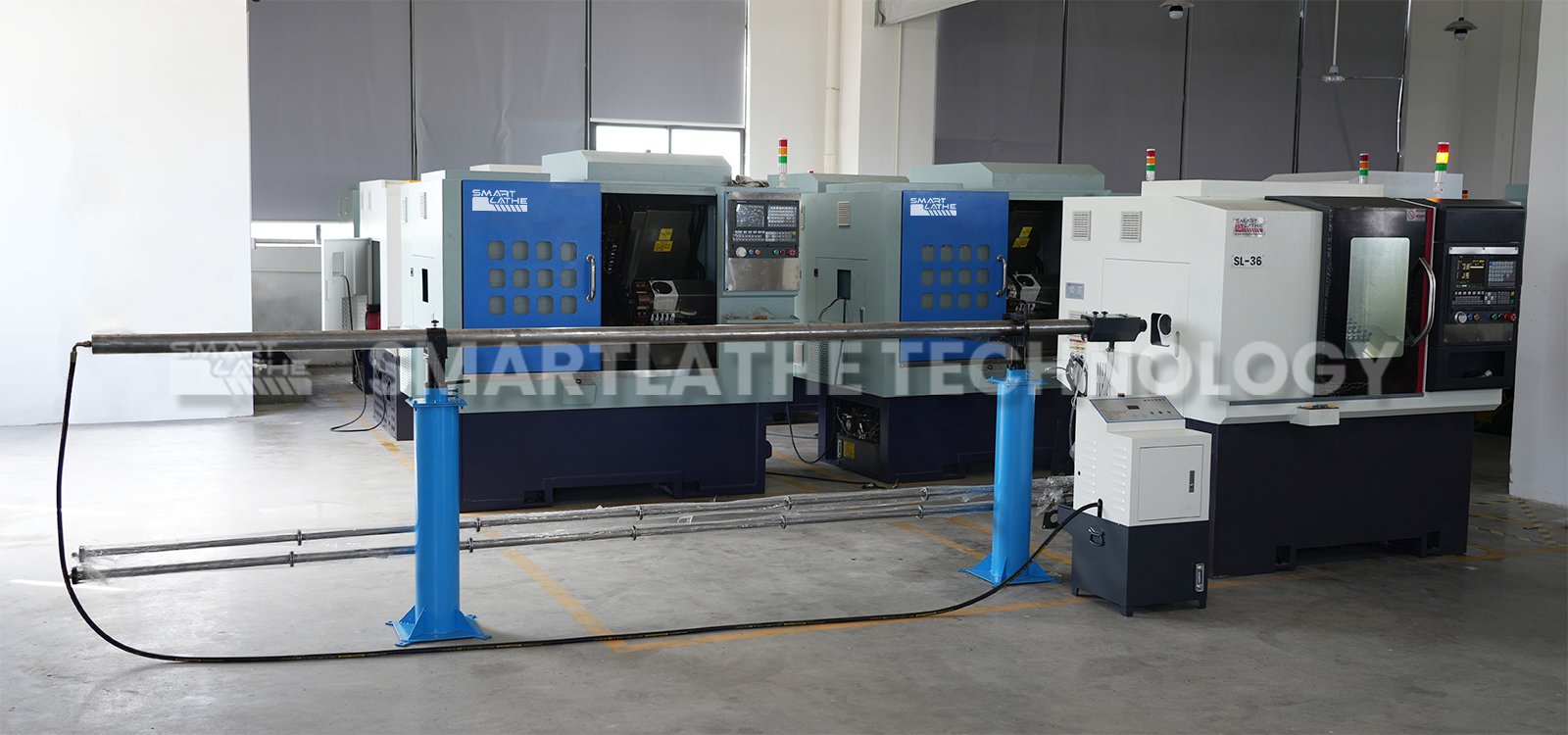
Selection of CNC Lathe Feeders
A CNC lathe feeder is an automated device used in machining processes, primarily to automatically feed materials into a CNC lathe for processing. Feeders offer advantages such as efficiency, stability, and cost savings in CNC lathe machining.
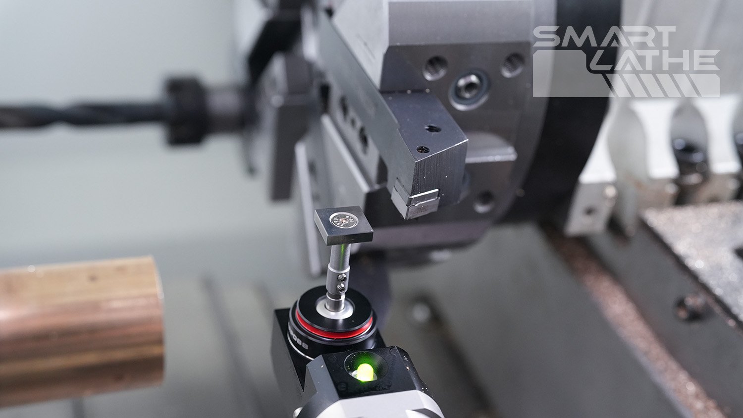
The application of tool setters on CNC lathes
On CNC lathes, the tool setter is a crucial device for ensuring the correct installation and positioning of tools, as well as monitoring and adjusting tool conditions.

Pneumatic transmission and hydraulic transmissions in CNC lathes
Pneumatic transmission utilizes gas, typically air, to transfer energy and is commonly employed for actuator driving in automation systems. Its characteristics include easy installation, low maintenance costs, and operational safety. Suitable for tasks like rapid tool changing, positioning, and clamping, it finds wide application across automation equipment, manufacturing, and industrial production lines. On the other hand, utilizes liquid, usually oil, to transfer energy, prevalent in power transmission and control within mechanical systems. Hydraulic transmission systems compress and flow liquid to achieve various actuator movements and controls, such as hydraulic cylinders and motors. Its characteristics include high load-carrying capacity, precise control, and high reliability. Hydraulic transmission is extensively used in heavy machinery, engineering equipment, automotive braking systems, providing effective power support across various industrial applications.

CNC lathe chuck types
CNC lathe is a type of high-precision, high-efficiency automated machining equipment. There are various types of chucks used on its spindle, which can be categorized based on their clamping methods and structural characteristics. The following are types of chucks commonly used on CNC lathes
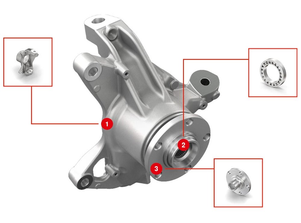
Application of CNC Lathe in the Field of New Energy Vehicles
The field of new energy vehicles is one of the key areas for the application of new energy technologies. With increasing global attention to environmental protection and climate change, the market for new energy vehicles is rapidly expanding. Electric vehicles have become the mainstream choice, with their sales increasing year by year. Major automobile manufacturers are introducing electric models, accelerating the development of the new energy vehicle industry chain. At the same time, technological innovations in electric vehicles, such as battery technology, charging technology, and intelligent driving technology, have made significant breakthroughs. Governments also encourage and promote the development of new energy vehicles through policy support and subsidies. In the future, with advancements in technology and reductions in costs, the field of new energy vehicles will have even broader development prospects, making greater contributions to reducing exhaust emissions and improving energy efficiency.
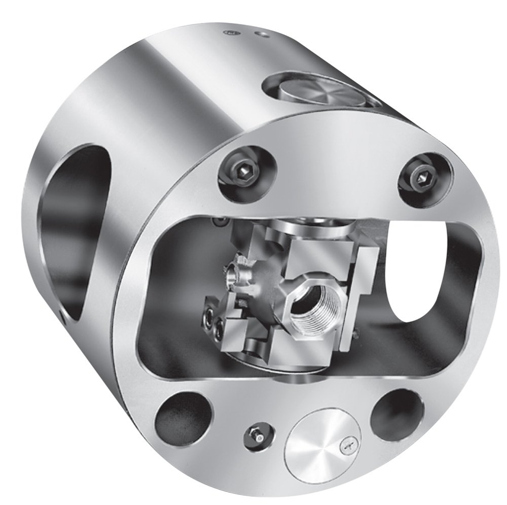
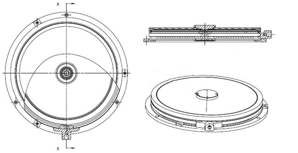
What is Indexing Chuck
The indexing chuck plays a crucial role in CNC lathe machining, serving as one of the key tools for achieving precise workpiece machining and efficient production.
In recognition of the machining advantages of indexing chucks, SMART LATHE has taken proactive steps to offer sales and customization services for indexing chucks, keeping pace with the times. Moreover, these indexing chucks are matched according to the CNC lathes available at SMART LATHE.
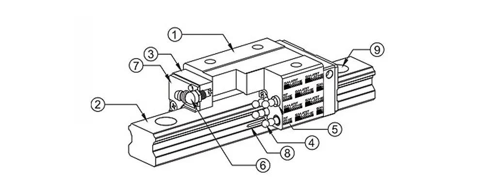
Types of Guideways in CNC Lathes
CNC lathes, as crucial equipment in modern manufacturing, often directly affect product quality and production efficiency. Guideways, as one of the core components of CNC lathes, play a vital role in the motion system of the machine. This article will explore common types of guideways in CNC lathes, with a focus on comparing linear guideways and V-type guideways, and analyzing their respective advantages and disadvantages.