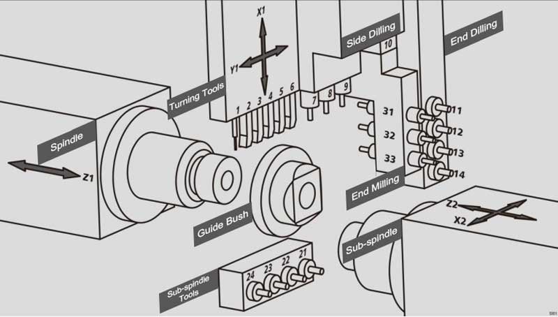
Double Spindle CNC Lathe with Guide Bushing or not.
The guide bushing in a Swiss-type lathe is used to guide and support the workpiece, ensuring its stability during the machining process and reducing vibration and displacement.
Due to the bending of the material or the forces generated during machining, if the machining part is far from the material clamping position, achieving high-precision cutting becomes difficult. Therefore, to machine long and slender products, a mechanism to support the material (the guide bushing) is installed between the chuck and the tool, allowing the chuck to move longitudinally along the material. Since the guide bushing supports the material near the tool, it reduces the bending of the material caused by machining forces, allowing high-precision machining with a Swiss-type lathe.
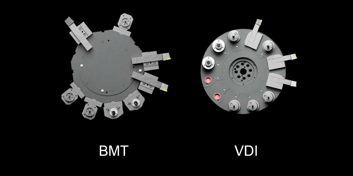
Differences Between BMT and VDI Turrets
In the field of CNC machine tools, BMT (Base Mount Turret) and VDI (Verband Deutscher Ingenieure) are two common types of turrets. They differ in terms of process, structure, precision, and operation, each suited to different machining needs. This article will provide a detailed comparison of these two turret types.
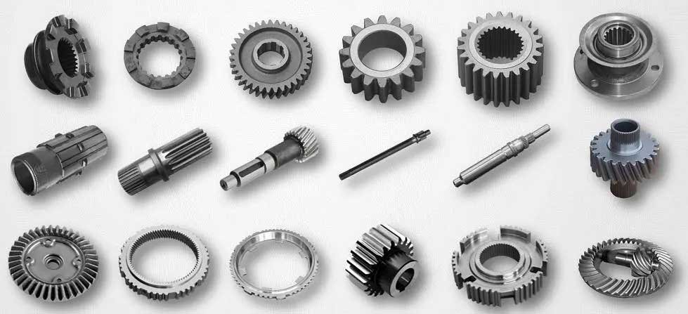
Classification of Gear Machining on CNC Lathes
Gear machining on CNC lathes is a crucial aspect of gear manufacturing, involving various machining methods and tools. Based on the machining method and the type of gear, CNC lathe gear machining can be primarily classified into: forming machining, gear hobbing, gear shaving, etc.
End Face Grooving
On CNC lathe, when machining end face grooves on the surface of a part, selecting the correct tool is crucial. The radius of the groove will determine the curvature of the tool. Since the groove is arc-shaped, chip removal can become an issue. Chips clogging the groove can lead to blade breakage, creating safety hazards.
Vibration Damping Principle of Cast Iron
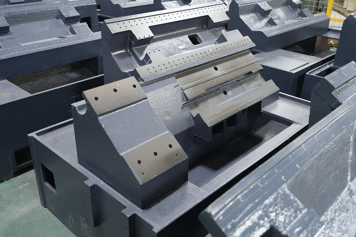
The material selection for the base of a CNC lathe is critical for ensuring the stability and precision of the machine. Commonly used materials for the base include cast iron, steel, and concrete. The base provides high rigidity and stability, absorbing vibrations during machining to ensure processing accuracy. The design of the base ensures the overall stability of the machine, reducing thermal and mechanical deformation, thus enhancing the machine's lifespan and machining quality.
Considering that CNC lathes prioritize stability and require strong vibration damping, cast iron is typically chosen for the base over steel. This is often achieved through integral molding, reducing the need for welding and assembly processes, lowering manufacturing costs, and improving production efficiency.
Calculation of Machining Time for Facing, Parting Off, and Deep Grooving on a CNC Lathe
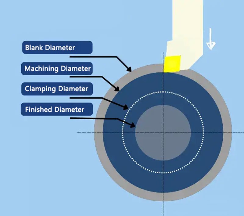
SMARTLATHE often needs to calculate machining times during the analysis of CNC lathe drawings. While CNC programming software can typically complete these calculations quickly, it is important for us to understand how the software performs these calculations.
Comparison of Helical Splines and Straight Splines
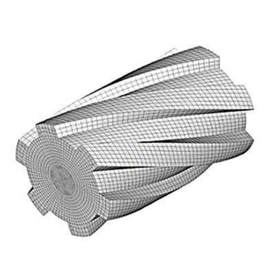
1.1 Helical Splines
The spline teeth are helical, similar to threads. The tooth surface is at a helical angle, with a smaller tooth profile angle. The design is more complex, and the manufacturing difficulty is higher.
1.2 Straight Splines
The spline teeth are straight, parallel to the spline axis. The tooth surface is parallel to the axis, with a simple tooth profile. The design is relatively simple, and manufacturing is easier.
Classification of geometric tolerances during CNC lathe machining—Guide rails
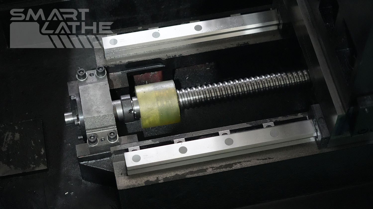
The geometric tolerances of CNC lathe guide rails have a significant impact on machining accuracy and workpiece quality. These tolerances mainly include horizontal straightness tolerance, vertical straightness tolerance, and parallelism tolerance of the guide rails.
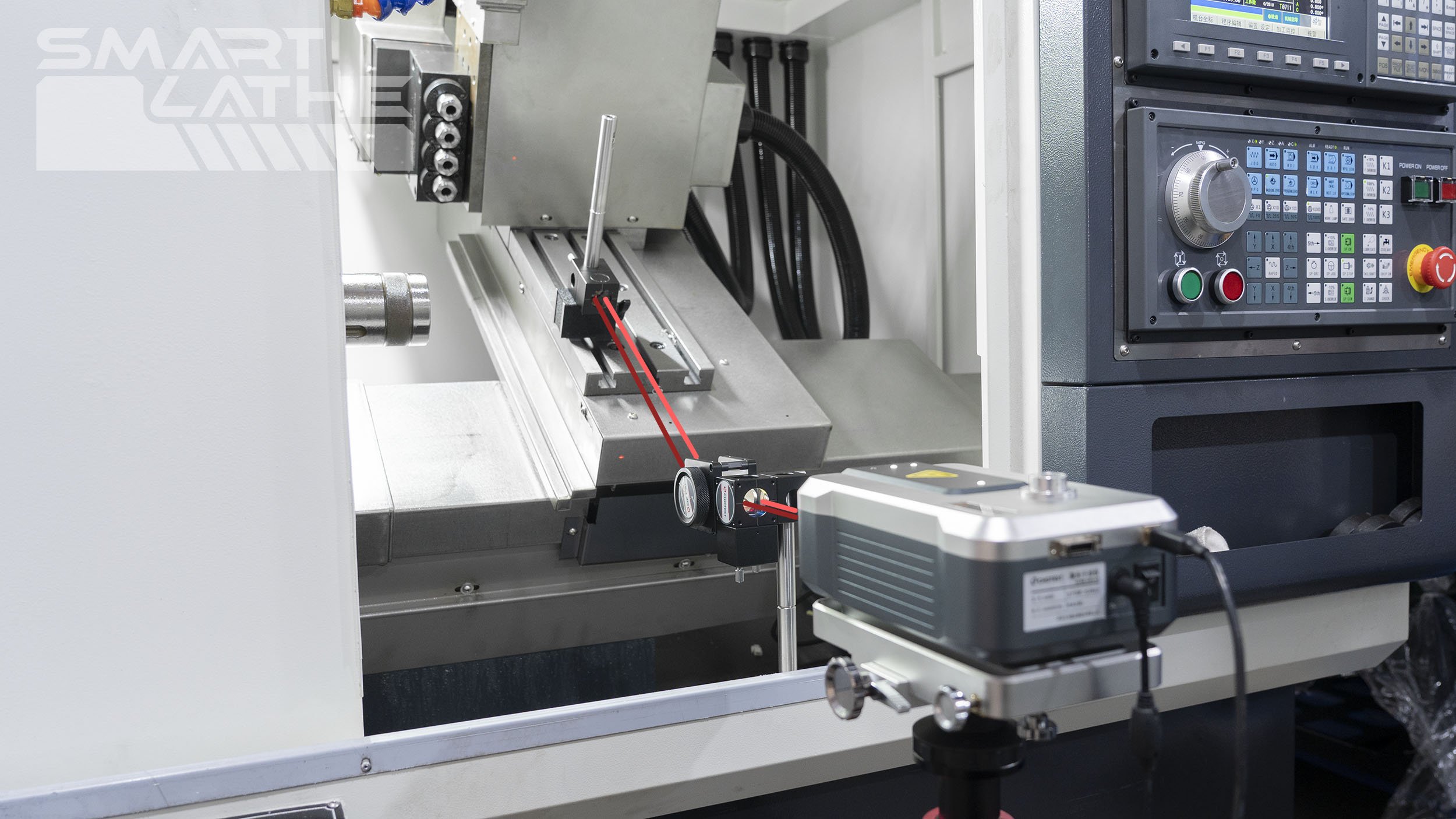
The Difference Between Positioning Accuracy and Repeatability in CNC Lathes
In CNC lathe operations, positioning accuracy and repeatability are two key parameters that directly affect machining quality and production efficiency. Understanding and correctly applying these concepts can help optimize the machining process and improve product quality. This article will detail these two concepts and their differences.

Selection of Threading Inserts for CNC Lathes
When performing threading on a CNC lathe, it is crucial to select the most suitable threading inserts for your application based on the insert type, flank/radial clearance, and insert profile. These factors significantly impact chip control, insert wear, tool life, and thread quality.

Adiabatic Shearing Phenomenon in High-Speed Cutting
In the field of precision manufacturing, high-speed cutting technology is highly regarded for its efficiency and precision. However, behind this technology lies a complex physical process known as the "adiabatic shearing phenomenon." So, what is the adiabatic shearing phenomenon in high-speed cutting? Today, let's unveil the mystery behind this technology.
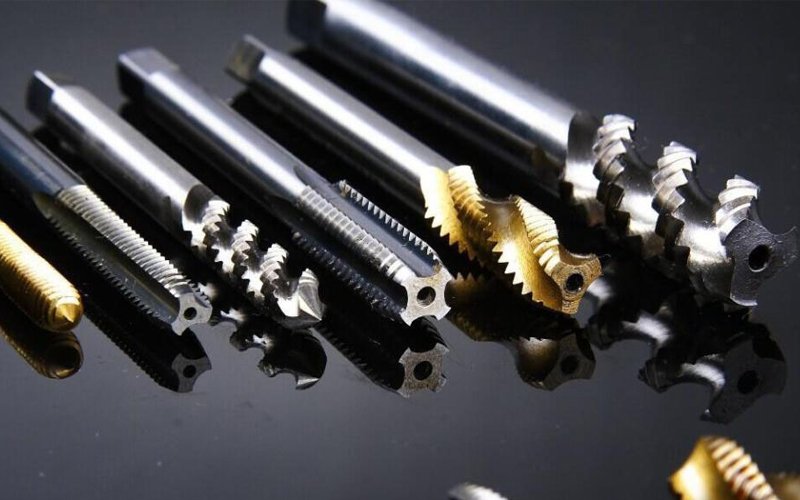
Common issues and solutions for rigid tapping
During the tapping process, various issues can arise that affect production techniques and efficiency. Today, we will analyze the solutions to common tapping problems.
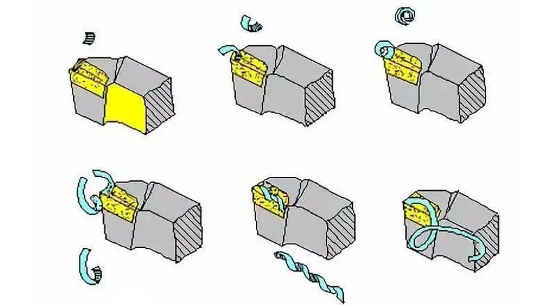
The Impact of Spindle Speed and Feed Rate on Chip Formation
In the world of CNC lathe, chip formation is a crucial indicator. It directly affects machining efficiency, tool life, and the quality of the finished product. When delving into chip formation, two critical factors come to the forefront: spindle speed and feed rate.
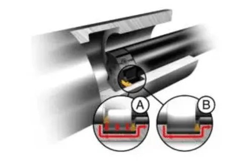
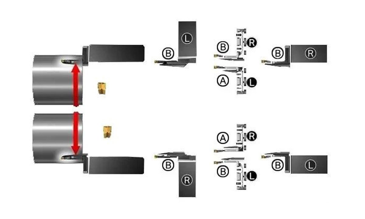
CNC Lathe Internal Grooving Process
The two main challenges in internal groove machining are excessive extension of the guide rod and poor chip removal. Excessive extension can lead to deflection and vibration issues. Vibration and poor chip removal can cause insert breakage. Difficulty in chip removal can also lead to poor surface finish. The most common internal groove machining process is radial grooving; however, multi-groove turning (A) and feed-in turning (B) can also be used.

Common Solutions for Tool Sticking on CNC Lathes for Various Materials
Tool sticking on CNC lathes refers to the phenomenon where the cutting tool adheres to the workpiece material during machining. This results in material buildup on the tool surface, affecting both the quality and efficiency of the machining process. To address this issue, it is essential to understand the properties of the materials and the causes of the phenomenon to provide suitable solutions.
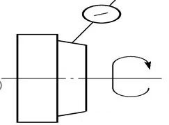
Geometric Accuracy of CNC Lathe
The straightness of the bed guide rails in the vertical plane after leveling the longitudinal guide rails.
Inspection Tool: Precision spirit level.
Inspection Method: Place the spirit level along the Z-axis on the carriage. Inspect at various positions along the entire length of the guide rail at equal intervals. Record the readings of the spirit level and document them in a report. Use the graphical method to calculate the straightness error of the bed guide rails in the vertical plane. The inspection schematic is as shown in the diagram.
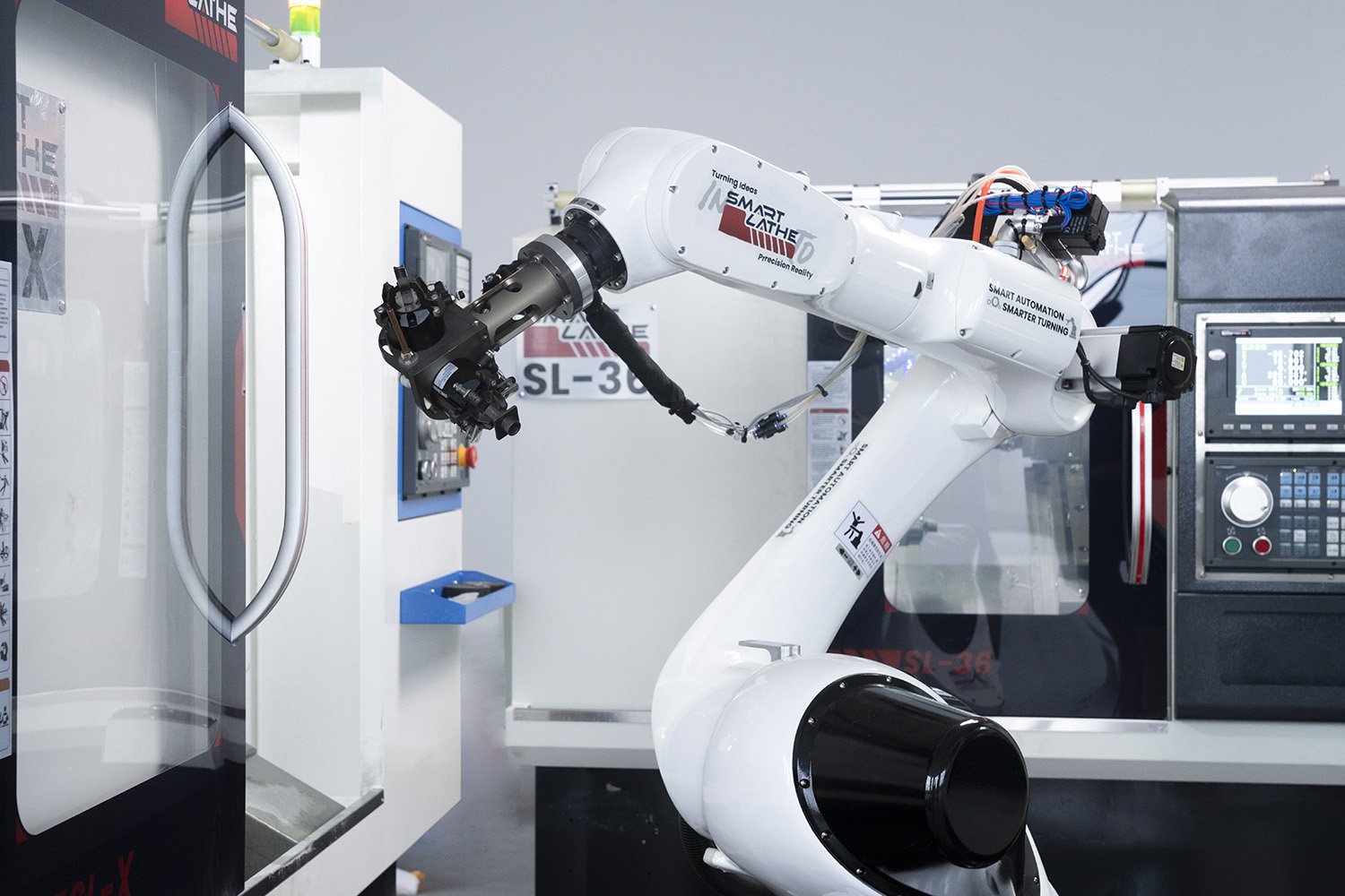
Application of Automated Robotic Arms in CNC Lathes
With the rapid advancement of technology, automation is increasingly being applied in the manufacturing industry. As a crucial component of this trend, the use of automated robotic arms in CNC lathes not only enhances production efficiency but also improves the precision and quality of products. This article will explore the application of automated robotic arms in CNC lathes and the numerous advantages they offer.
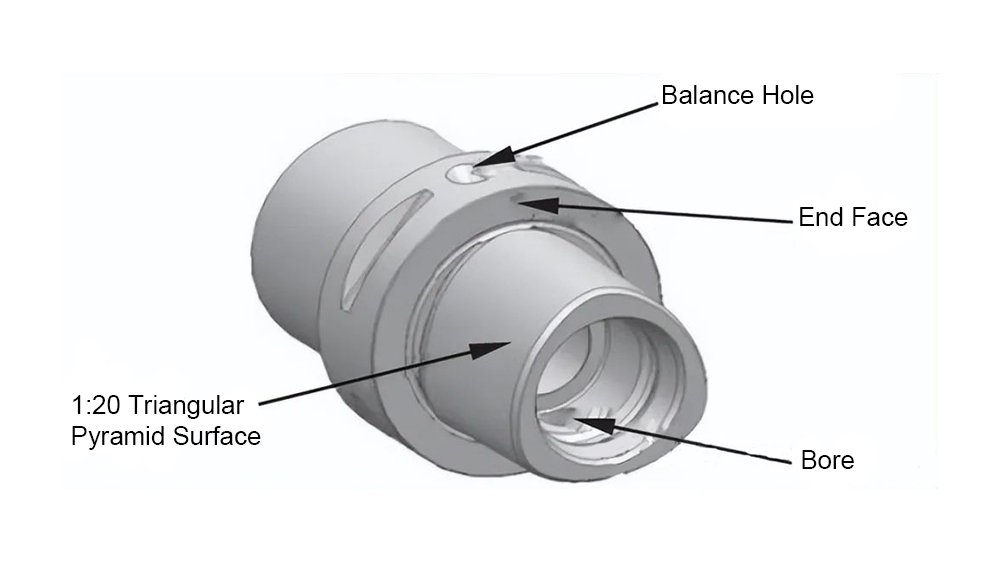
What is capto tool holder?
Capto is a double-sided locating hollow tapered tool holder, available in seven models: C3, C4, C5, C6, C8, C8x, and C100, each corresponding to a different diameter. The cross-section of the Capto tool holder features three evenly spaced curved surfaces, with three convex edges distributed uniformly at 120° intervals around the circumference. This design maximizes contact surface area, minimizes stress concentration, reduces deformation and wear, ensures more even force distribution, allows for greater torque transmission, and enhances precision in positioning.

Common Tolerances on CNC Lathes
Tolerances on CNC lathes refer to the allowable deviation range between the shape and position of the part during the machining process and the design requirements. Tolerances consist of shape tolerances and positional tolerances. Shape tolerances refer to the shape deviations between different parts of the part, such as straightness, roundness, cylindricity, etc. Positional tolerances refer to the positional deviations between different parts of the part, such as parallelism, perpendicularity, coaxiality, etc. CNC lathes achieve high-precision tolerances by controlling tool motion trajectories and machining parameters, ensuring the quality and accuracy of the parts.
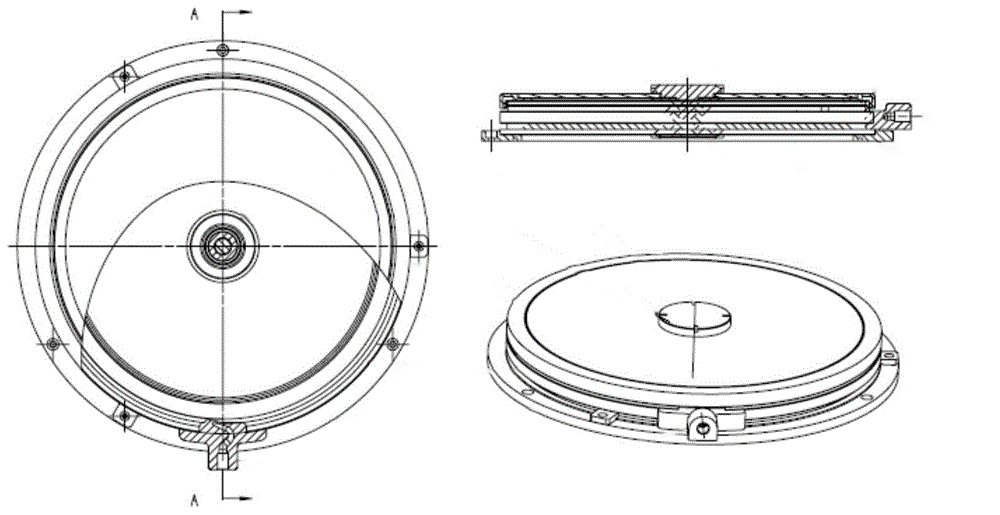
Spin Window on CNC Lathes
The introduction of the Spin Window has improved the efficiency and safety of CNC lathes, as well as enhanced the operational efficiency and skill level of operators.
Following a series of technical evaluations, SMARTLATHE has proposed an electrically operated visual observation window solution.
